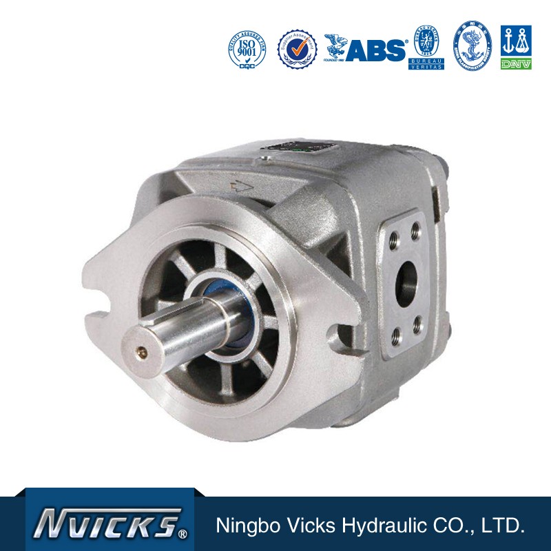
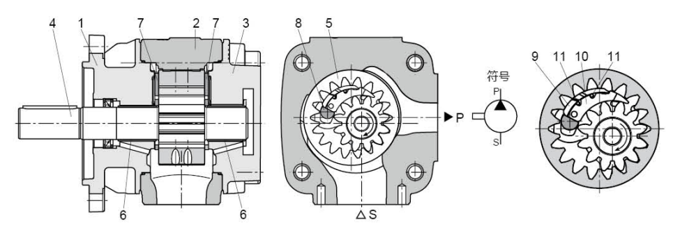
Priciple Diagram of Gear Pump
The VG hydraulic pump is a backlash compensation internal gear pump with a fixed displacement. Its basic structure is: intall front cover (1), pump body (2), rear cover (3), outer gear shaft (4), inner gear ring (5), sliding bearing (6), oil distribution plate (7), and positioning rod(8), an consist of crescent sub-board (9), crescent main board (10) and sealing rod (11)
Suction and spiling process
The external gear shaft (4) installed according to fluid dynamics drives the internal gear ring (5) in the direction of rotation shown. Fill the oil through the tooth gap opened in the oil suction area. The oil is transported from the oil suction area (S) to the pressure area (P) through the side clearance between the outer gear shaft and the inter gear ring. As a result, the oil is discharged from the closed tooth gap and delivered to the pressure oil port (P). The oil suction area and the discharge area are separated by the radial compensation element (9 to 11) and the gear mesh between the inner the inner ring gear and the outer gear.
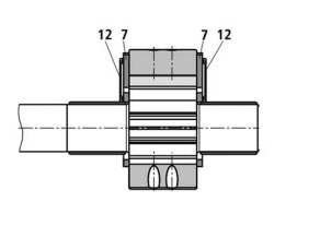
Axial compension
The discharge chamber in the pressure zone is axially sealed by tge iuk distribution plate (7). The oil distribution pan faces away from the discharge are one side is back pressured by the pressure filed (12). These pressure fields make the oil distribution plate and the discharge area reach a balance, from the ideal sealing effect is achieved with lower mechanical loss.
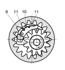
Radial compensation
The radial compansation element includes a crescent sub-plate(9), a crescent main plate (10) and a sealing rod (11). The crescent main plate (10) to the round surface of the booth tip of the outer gear shaft, the crescent sub-plate (9) is closely attached to the round surface of the tooth tip of the inner gear ring, and the positioning rod is used to restrict the movement of the crescent plate in the circuferential direction.
In this way, the pressure zone can be separeated from the suction zone by automatic clearance adjustment. This is a prerequissite for maintaining high volumetric effeciency continuously throughout the working hours.
Toothing
The toothing with involute flanks features a long meshing length for low flow and pressure pulsation and therefore ensures low noise operation.
Model Designation
| VG1 | -63 | R | E | W | -A1 |
| Series | Displacement ml/r | Rotation | Shaft type | Sealing material | Design No. |
| VG0 | 8,10, 13, 16, 20, 25 | Views from the shaft end of pump R= Right hand for clockwise L=Left hand for counter-clockwise |
E=straight key shaft R=Spline shaft |
W= NBR V=FKM |
A1 |
| VG1 | 25, 32, 40, 50, 63, 50H, 63H | ||||
| VG2 | 80, 100, 125, 145, 160 |
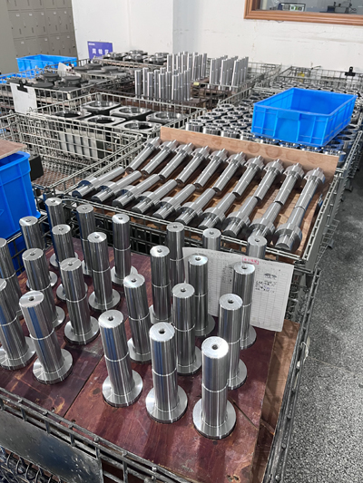
Shafts for pump
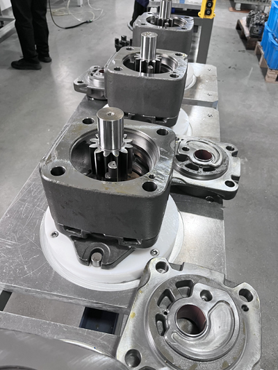
Assembling the pump
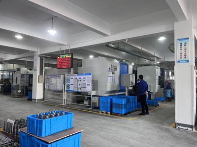
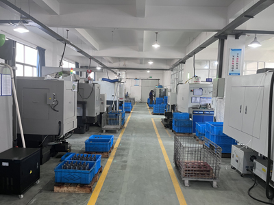
Views of workplace
6S Management
Application
It can be widely used in industry, such as plastic machine, shoe machine, die casting machinery and forklift and other industries hydraulic system, especially for servo variable frequency drive energy saving system
Points for attention to use
1. Oil pump installation
- As far as possible, flexible coupling is used for connection between pump shaft and motor shaft to avoid bending moment or axial thrust. The maximum allowable coaxiality error between pump shatf and motor shaft is 0.15mm.
2. Inlet and outlet connection
- Select the inner diameter of the pipeline according to the oil port of the oil pump ( the optimal inlet velocity is 0.6-1.2m/s );
- The design dimensions of the suction tubing line must comply with the allowable inlet working pressure (absolute value of 0.8bar to 2bar), and must avoid bending the suction tubing line and the combination of several pump suction tubing;
- If the oil suction fliter is used, it is recommended that the oil suction filter be selected according to the maximum flow of the oil pump, multiplied by the coefficient of 2-3 times, and the absolute filteration accuracy is 50-180um. It must be ensured that even if the filter is polluted, it will not exceed the minimum allowable inlet working pressure of the system;
- The immersion depth of the selected suction tubing should be as deep as possible. Eddy currents should not be formed even at the maximum flow rate, otherwise it will be a risk of air suction and release.
- In the design of suction pipe, the oil inlet is not recommended to be installed vertically downward. If the oil tank is located below the oil pump, the oil inlet should be up or on both horizontal sides.
3. The combination of pump
- When combining pumps, it is necessary to ensure that each stage complies with the allowable working date of the relevant pump types;
- The rotation direction of all combined pumps must be the same;
- Pumps with maximum torque, variable displacement or applied load shall be provides as the first stage of the combined pump;
- Maximum shaft drive torque must be checked by the project planner for various applications.
Maxmum permissible torque (Nm)
The total torque of the combined pump shall not exceed the maximum driving torque.
Combination inhalation is not allowed.
Rear pump shaft design must be "R" (spline).
4. Initial operation
- Check whether the hydraulic system is properly installed and connected at the intial start;
- Before operation, should through the suction tubing or flowline for internal filled with hydrailic oil pump, oil relief valve, open the system under the condition of no load operating motors, stay sufficient lubrication oil pump, and discharge the air in the piping (oil is not set the relief valve, such as system can use the pump export joint relax a little, some methods, for exhaust gas leak. When bubbles no longer appear in the leaked oil, the loosened part shall be locked according to te specified torque. Note: when using this method, it must ne under low pressure condition and ensure that te pressure does not rise. )
- Unable to start loading, otherwise it will cause internal damage of the oil pump.
- After repeated dot operation, the suction sound will disappear. If the air mixing sound does not disappear after repeated dot operation for several times. It should be that there is air leakage in the pipeline at the inlet side.
5. Maintenance
- In order to improve the service lift of the oil pump, the abnormal vibration, noise, oil temperature, oil condition of the hydraulic system, whether there are bubbles in the tank and whether there are leaks and other problems should be checked regularly and maintained in time;
- All the oil pumps have passed the performance test before leaving the factory. Any enterprise or individual shall not disassemble, reassemble or transform the oil pumps without the permission of the company. If disassemble, reassemble or transform the oil pumps without permission of the company, it is not within the scope of the company's repair report and the company shall not assume any reponsibility.