Hydraulic vane pump failure most often results from fluid contamination, cavitation, aeration, excessive heat, incorrect installation, misalignment, or operation beyond the pump’s design limits. The fastest troubleshooting method is to compare symptoms with suction conditions, fluid cleanliness, temperature, pressure, shaft alignment, and vane or cartridge wear before replacing the pump.
- Contaminated hydraulic fluid accelerates wear on vanes, cam rings, pressure plates, and cartridge components.
- Cavitation and aeration usually begin in the inlet circuit and can cause noise, vibration, erosion, and unstable output.
- Correct diagnosis should separate installation faults from internal mechanical wear.
- Routine checks of filtration, fluid level, temperature, alignment, and pressure can prevent many pump failure causes.
Hydraulic vane pump failure is rarely caused by one isolated component. It commonly develops through a chain involving poor fluid condition, restricted inlet flow, excess heat, incorrect pressure settings, or installation errors. A pump failure analysis resource reports that aeration, cavitation, contamination, and excessive heat account for approximately 90 to 95 percent of pump failures in the applications it discusses; review the source context before applying that figure to a specific machine. This guide explains the failure mechanisms, diagnostic sequence, repair decisions, and prevention practices that support reliable vane pump troubleshooting.
1. Contaminated Hydraulic Fluid
Contamination is the most common preventable cause of vane pump damage because abrasive particles can pass through the working clearances and remove material from precision surfaces. Dirt, metal particles, degraded seals, water, and chemical by-products can damage vanes, cam rings, side plates, pressure plates, and shaft seals.
Particle contamination is especially harmful when it enters through a damaged breather, open reservoir, poorly maintained filter, or dirty service equipment. As clearances increase, internal leakage rises and the pump may lose flow, pressure stability, and volumetric efficiency. The vane pump troubleshooting booklet from HOF identifies contamination among the major incidents requiring investigation; its discussion begins in the chapter listed as “The most common causes.”
The first response should be to identify the contaminant rather than simply replace the pump. Inspect the filter element, reservoir, suction strainer, hose interiors, and failed components. If metal is present, determine which part generated it, because a new pump can fail quickly when debris remains in the circuit.
- Check whether the filter is installed in the correct flow direction.
- Inspect the breather and reservoir cover for unfiltered air entry.
- Drain a representative fluid sample using clean sampling equipment.
- Flush contaminated lines and clean the reservoir before installing replacement parts.
- Confirm that replacement seals and hoses are compatible with the selected fluid.
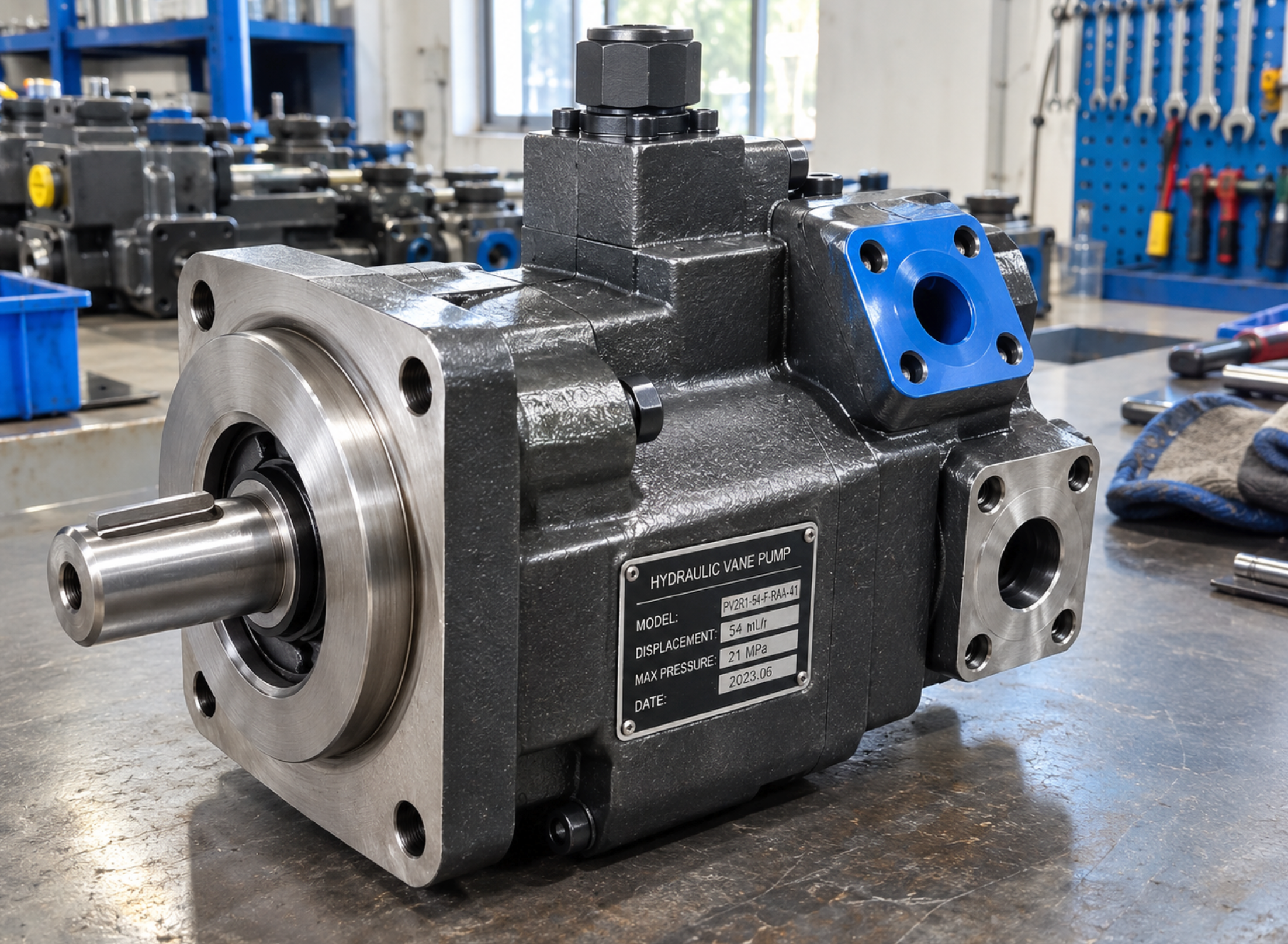
2. Cavitation and Inlet Restriction
Cavitation occurs when the pump inlet cannot supply fluid fast enough to fill the expanding chamber, causing vapor bubbles to form and collapse inside the pump. Typical contributors include a blocked suction strainer, undersized inlet hose, excessive fluid viscosity, low reservoir level, a closed isolation valve, or excessive suction lift.
Cavitation usually produces a sharp buzzing or gravel-like sound, vibration, fluctuating pressure, and progressive erosion. The Hydraulic Supermarket explanation notes that excessive vacuum at the pump inlet can act at the base of the vane and cause the vanes to lose contact with the cam ring. That loss of contact can reduce output and increase impact loading when contact is restored.
The inlet circuit should be checked before adjusting the relief valve or replacing internal parts. Measure inlet vacuum under actual operating conditions, inspect every connection for restriction, and compare fluid viscosity and temperature with the pump manufacturer’s requirements.
| Diagnostic check | Sequence number | What to inspect | Failure indication |
|---|---|---|---|
| Reservoir level | 1 | Fluid level during operation | Inlet exposure or vortex formation |
| Suction path | 2 | Hose, strainer, valve, and fittings | Restriction, collapse, or blockage |
| Fluid condition | 3 | Viscosity, foaming, and temperature | Slow filling or vapor formation |
| Inlet measurement | 4 | Vacuum under working load | Excessive inlet vacuum |
3. Aeration and Air Leaks
Aeration occurs when air enters the hydraulic fluid, while an air leak can pull air into the suction line without producing an obvious external fluid leak. The result is foamy fluid, erratic actuator movement, noise, vibration, and reduced pump life.
Common entry points include loose suction fittings, cracked hoses, hardened O-rings, a low reservoir level, a poorly sealed shaft area, or a return line that discharges above the fluid surface. Machinery Lubrication explains that suction-side air leaks may result from a loose connection, cracked line, or improper installation.
The most reliable check is to inspect the entire inlet path while the system is operating at the condition that produces the symptom. Tightening fittings alone may not solve the problem if a hose has become brittle or if the fitting seal is incompatible with hydraulic fluid.
- Look for foam, milky fluid, or a translucent stream in the reservoir.
- Listen for a rattling or unstable pump sound.
- Inspect suction fittings, hose ends, clamps, and O-rings.
- Verify that the return line remains below the fluid surface where the design requires it.
- Correct the air source, then remove trapped air according to the machine procedure.
4. Excessive Heat and Poor Fluid Condition
Excessive heat reduces fluid viscosity, accelerates seal deterioration, and increases oxidation and varnish formation. Heat can be generated by excessive pressure, a continuously bypassing relief valve, undersized plumbing, restricted coolers, high internal leakage, or an incorrectly selected fluid.
Heat-related damage often appears as hardened or brittle seals, darkened fluid, varnish deposits, noisy operation, and declining performance after the machine reaches operating temperature. A pump that performs normally when cold but loses pressure or flow when hot should be investigated for internal leakage and thermal loading rather than treated as an immediate cartridge replacement case.
The correct remedy is to locate the heat source. Check pressure at the pump outlet, verify relief valve operation, inspect cooler airflow or water flow, and compare actual fluid viscosity with the pump maker’s approved range. Do not compensate for overheating by installing a higher-pressure setting without confirming system design limits.
5. Misalignment, Incorrect Installation, and Shaft Loading
Misalignment transfers abnormal radial or axial forces into the pump shaft, bearings, coupling, and seal. These loads can create seal leakage, bearing wear, coupling damage, vibration, and accelerated cartridge wear even when the hydraulic fluid is clean.
Installation problems include an unsupported suction line, excessive coupling misalignment, incorrect rotation, insufficient shaft engagement, over-tightened mounting hardware, and pipe forces transmitted into the pump body. The HOF troubleshooting booklet lists misalignment among the major incidents associated with vane pump problems.
Installation should be checked against the pump and machine manuals, with particular attention to rotation direction, coupling fit, mounting faces, shaft alignment, and pipe support. A replacement pump should not be commissioned until the original installation cause has been addressed.
6. Excessive Pressure, Speed, or Mechanical Wear
Operating outside the rated pressure, speed, temperature, or fluid conditions accelerates wear even when the system appears to function normally. Excessive pressure can burn or score pressure plates, while excessive speed can increase inlet demand, heat generation, and centrifugal loading.
Normal wear is also expected in vanes, cam rings, side plates, bearings, seals, and cartridge kits. Wear becomes a failure when clearances allow excessive internal leakage, the vane tips no longer maintain effective contact, or pressure and flow fall below the machine requirement.
Use measured operating conditions rather than assumptions during diagnosis. Record pressure at idle and under load, observe performance cold and hot, and compare measured speed and fluid condition with the applicable manufacturer documentation. Repair may be appropriate when the housing and shaft are serviceable; replacement is safer when critical surfaces are deeply scored, distorted, or repeatedly damaged by contamination.
| Symptom | Check 1 | Check 2 | Likely direction |
|---|---|---|---|
| Grinding or buzzing noise | Inlet restriction | Air entry | Cavitation or aeration |
| Low flow when hot | Fluid viscosity | Internal leakage | Heat or wear |
| External shaft seal leak | Alignment | Shaft and bearing condition | Mechanical loading or seal damage |
| Unstable pressure | Foaming | Relief valve and contamination | Aeration or control problem |
| Rapid repeat failure | Debris source | Installation records | Uncorrected root cause |
Vane Pump Troubleshooting: A Practical Decision Process
A structured diagnosis prevents unnecessary replacement and protects the new pump from the same failure mechanism. Begin with operating evidence, then move toward disassembly only after external causes have been tested.
- Make the machine safe. Isolate energy, release stored pressure, and follow the equipment maintenance procedure.
- Record symptoms. Note noise, temperature behavior, leakage, pressure instability, response time, and the point at which the fault appears.
- Check the inlet circuit. Verify level, hose condition, strainer condition, valve position, vacuum, and fluid viscosity.
- Check fluid quality. Inspect for particles, foam, water, discoloration, and unusual odor.
- Check installation. Confirm rotation, coupling alignment, shaft loading, pipe support, and mounting condition.
- Check operating demand. Compare actual pressure, speed, temperature, and duty cycle with the approved pump data.
- Inspect removed parts. Look for scoring, erosion, heat discoloration, broken vanes, hardened seals, and abnormal contact patterns.
How to Prevent Hydraulic Vane Pump Failure
Prevention depends on controlling the fluid, the inlet circuit, the operating envelope, and the installation quality as one system. A clean pump cannot compensate for a restricted suction line, and a correctly aligned pump cannot survive persistent abrasive contamination.
- Keep the reservoir closed and use a suitable breather.
- Maintain filtration and replace elements according to condition and machine requirements.
- Inspect suction hoses and fittings during scheduled service.
- Monitor fluid temperature, pressure, noise, and performance trends.
- Support hydraulic piping so pump ports do not carry external loads.
- Use compatible replacement cartridges, seals, and fluid.
- Investigate every failed component for the initiating cause before returning the machine to service.
Frequently Asked Questions
1. What is the most common cause of vane pump failure?
Contaminated hydraulic fluid is one of the most common causes because abrasive particles damage precision surfaces and increase internal leakage. However, the actual root cause should be confirmed through fluid inspection, filter review, and component examination.
2. How can I tell whether a vane pump is cavitating?
Cavitation commonly produces a sharp buzzing or gravel-like sound, vibration, unstable flow, and inlet-side vacuum symptoms. Check fluid level, suction restrictions, strainer condition, hose sizing, and fluid viscosity before replacing the pump.
3. Can air in the hydraulic system damage a vane pump?
Yes. Aerated fluid reduces lubrication quality and can cause noise, vibration, unstable pressure, and surface damage. Inspect suction fittings, hoses, seals, reservoir level, and return-line placement.
4. Why does a vane pump lose pressure when hot?
Common explanations include excessive fluid temperature, low hot viscosity, internal wear, a bypassing relief valve, or heat generated elsewhere in the circuit. Compare cold and hot performance and measure pressure under the same load.
5. Should I replace the whole pump or only the cartridge?
A cartridge or pump core may be suitable when the housing, shaft, bearings, and mounting interfaces remain serviceable. Full replacement is more appropriate when the housing is scored, the shaft is damaged, or the failure source could contaminate a repaired assembly.
6. Can incorrect alignment cause a shaft seal leak?
Yes. Coupling misalignment, shaft loading, bearing wear, or mounting stress can overload the seal and create repeat leakage. Correct alignment and inspect the shaft before installing another seal.
7. What should be checked after installing a replacement vane pump?
Verify rotation, inlet filling, fluid level, filtration, coupling alignment, pressure settings, operating temperature, and leakage. Start under controlled conditions and monitor noise and pressure before returning the machine to full duty.
Hydraulic Replacement and Support
Vicks Hydraulic provides hydraulic power solutions covering vane pumps, hydraulic motors, servo systems, compatible replacement products, pump cartridges, and service parts. Its product focus supports legacy equipment replacement, international sourcing, and system matching for applications such as injection molding, mobile machinery, and industrial hydraulic circuits. When a failure requires replacement rather than repair, provide the original model, operating pressure, speed, fluid type, rotation, application, and failure symptoms so the correct configuration can be evaluated.
Use the linked technical references for additional troubleshooting context: review inlet-related vane pump failure guidance, consult the vane pump troubleshooting booklet, and read hydraulic pump troubleshooting guidance on aeration.

Demi Ge
Post time: Oct-27-2026