TL;DR: For hydraulic press and injection molding machine applications, the servo drive and servo motor integration directly affects the energy efficiency, the production cycle time, and the product quality. The correct servo drive specification depends on the pump displacement, the system pressure, the cycle duty, and the response time requirement. This guide walks procurement teams at hydraulic press manufacturers, injection molding machine builders, and industrial hydraulic system integrators through the three servo drive integration specifications that drive energy efficiency and production productivity.
I’ve spent the past 10 years at Vicks Hydraulic (Ningbo Vicks Hydraulic Machinery) supporting hydraulic system projects across more than 40 countries, with particular depth in hydraulic press systems, injection molding machine hydraulic systems, and industrial hydraulic power units. Our facility has supplied hydraulic pumps, hydraulic valves, and hydraulic system components for hydraulic press installations and injection molding machine installations across Asia, Europe, and the Americas. In that time, I’ve supported servo drive and servo motor integration projects ranging from 50-ton hydraulic press retrofits to 4,000-ton compression molding press installations.
The servo drive and servo motor integration is a technically demanding application that directly affects the energy efficiency and the production productivity of hydraulic equipment. The integration specification depends on the pump displacement, the system pressure, the cycle duty, the response time requirement, and the closed-loop control architecture. This guide covers the three servo drive integration specifications I see most often mis-specified, with the engineering rationale behind the correct specification, the impact of incorrect specification, and the sourcing questions you should be asking any servo drive and hydraulic pump manufacturer before placing the order. For the Vicks Hydraulic servo system range, the standard configuration covers the major hydraulic press and injection molding machine applications.
1. Why Servo Drive Integration Specification Is Equipment and Application Specific
Servo drive and servo motor integration with hydraulic pumps and hydraulic systems is a well-established technology for reducing energy consumption in hydraulic equipment. The servo drive controls the servo motor speed and torque to match the hydraulic pump output to the actual hydraulic system demand, eliminating the constant-pressure throttling losses that characterize conventional hydraulic systems with fixed-speed pump motors.
This is because the three major hydraulic equipment applications (hydraulic press, injection molding machine, and industrial hydraulic power unit) have fundamentally different duty cycles, pressure profiles, and response time requirements. Hydraulic presses require high pressure for the compression stroke and low pressure for the rapid traverse and return stroke, with cycle times typically 10–60 seconds. Injection molding machines require variable pressure and flow throughout the injection cycle (clamping, injection, holding, cooling, plasticizing), with cycle times typically 15–120 seconds. Industrial hydraulic power units require relatively constant pressure and flow for continuous-duty applications, with response time measured in milliseconds.
Therefore, a servo drive and servo motor specification that works for one application is typically inadequate for the other applications. The optimal servo drive specification for a hydraulic press is different from the optimal specification for an injection molding machine, which is different from the optimal specification for an industrial hydraulic power unit. Manufacturers that attempt to use one servo drive configuration across all three applications typically compromise on energy efficiency, cycle time, or response time, and the operational cost shows up in higher electricity consumption, lower production throughput, and reduced product quality consistency.
1.1 How Vicks Hydraulic approaches servo drive and hydraulic pump manufacturing
Before walking through the three specifications, a quick note on Vicks Hydraulic’s vertically integrated manufacturing capability. We operate the complete production chain in-house: hydraulic pump machining → hydraulic valve assembly → electric motor assembly → servo drive integration → hydraulic power unit assembly → testing → certification. The input specification for a servo drive and hydraulic pump order typically includes: (1) the application (hydraulic press, injection molding machine, industrial hydraulic power unit, or other hydraulic equipment), (2) the pump displacement (typically 16 cc/rev to 250 cc/rev for hydraulic press applications and 45 cc/rev to 500 cc/rev for injection molding machine applications), (3) the system pressure (typically 200 bar to 700 bar), (4) the cycle duty (cycle time, load profile, and continuous-duty ratio), and (5) the response time requirement (typically 20–50 ms for press applications and 5–20 ms for injection molding machine applications).
From those inputs, the Vicks Hydraulic engineering team produces a project proposal with: (1) a servo motor and servo drive model selection matched to the application requirements, (2) a hydraulic pump model selection matched to the pressure and flow requirements, (3) a system efficiency calculation for the target duty cycle, and (4) a lead time estimate from order confirmation to first delivery. The typical lead time from order confirmation to first delivery is 20–35 working days for standard servo drive and pump packages, and 45–60 working days for custom or large-capacity configurations. For energy efficiency reference, the Eurovent Certified Performance (ECP) for hydraulic systems framework provides the relevant international efficiency certification reference for servo hydraulic systems.
2. Specification #1 — Servo Motor and Pump Match for Hydraulic Press Applications
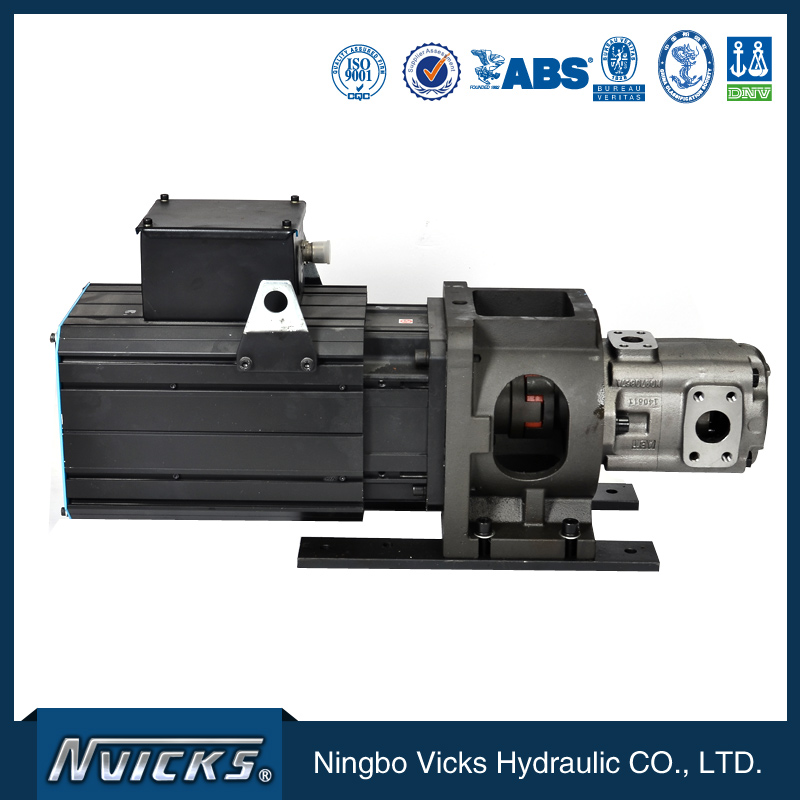
The first servo drive integration specification is the servo motor and hydraulic pump match for hydraulic press applications. The hydraulic press servo drive system must provide sufficient torque to drive the hydraulic pump to the system pressure under the peak load condition (compression stroke), and sufficient speed to provide the rapid traverse flow rate for the low-pressure strokes (rapid advance and return stroke).
2.1 Why peak torque specification matters for press applications
The peak torque requirement for a hydraulic press servo motor is determined by the maximum system pressure and the pump displacement. For a pump displacement of 100 cc/rev and a maximum system pressure of 350 bar (typical for a 1,000-ton hydraulic press), the peak torque requirement is approximately 580 Nm (calculated as pump displacement × maximum pressure / (2π × 60)). The servo motor peak torque rating must exceed this calculated value with a 20–30% safety margin.
The most common servo motor specification mistake I see is undersizing the servo motor peak torque rating based on the average torque requirement rather than the peak torque. The average torque for a press application is significantly lower than the peak torque (typically 30–50% of peak for most press duty cycles), and a servo motor sized for the average torque will saturate during the compression stroke and trigger the over-current protection, stopping the press. The fix is to specify the servo motor peak torque to the maximum system pressure and pump displacement combination.
2.2 The pump displacement specification for press cycle time
The pump displacement determines the maximum flow rate from the servo motor at the rated motor speed. For a hydraulic press with a 100 cc/rev pump driven by a servo motor at 3,000 rpm, the maximum flow rate is approximately 300 liters per minute. This flow rate determines the rapid traverse speed (typically 100–300 mm/s for press applications) and the return stroke speed (typically 200–500 mm/s).
For high-cycle-rate press applications (typically 8–15 cycles per minute for stamping presses and 3–8 cycles per minute for compression molding presses), the pump displacement must be sufficient to deliver the required flow rate at the servo motor rated speed. The Vicks Hydraulic engineering team typically specifies a variable-displacement pump (typically a load-sensing axial piston pump) in combination with the servo motor for press applications, with the load-sensing feature matching the pump output to the system demand and providing additional energy savings beyond the servo motor speed control.
Because the servo motor and pump match directly affects the press cycle time and the energy efficiency, therefore the servo motor and pump sizing is one of the most important decisions in the press servo drive integration. The cost premium for the correctly sized servo motor and pump combination is typically 25–40% above the undersized combination, but the reduced cycle time and the energy savings pay back the premium in 12–24 months of typical press operation.
3. Specification #2 — Servo Drive Response Time for Injection Molding Machines
The second servo drive integration specification is the servo drive response time for injection molding machine applications. The injection molding machine servo drive system must provide rapid pressure and flow control response throughout the injection cycle, particularly during the injection phase (typically 50–500 ms) and the holding phase (typically 2–20 seconds).
3.1 Why response time matters for injection molding quality
The response time of the servo drive and hydraulic system directly affects the injection speed profile, the holding pressure stability, and the finished part quality. A slow response time (typically >50 ms) results in injection speed fluctuations that affect the part surface finish, the part weight consistency, and the dimensional accuracy. A fast response time (typically <20 ms) provides stable injection speed and holding pressure, which improves the part quality consistency and reduces the reject rate.
The most common response time specification mistake I see is using a general-purpose servo drive (typically with 30–50 ms response time) for high-precision injection molding applications. The general-purpose servo drive is adequate for standard injection molding applications but is inadequate for high-precision applications (such as optical lens molding, medical device molding, and precision electronic component molding) that require response times of 10–20 ms or better.
The Vicks Hydraulic servo drive range includes: (1) standard servo drives with 30–50 ms response time for general injection molding applications, (2) high-performance servo drives with 10–20 ms response time for precision injection molding applications, and (3) custom servo drives with customized response time for specific OEM requirements. The cost premium for the high-performance servo drive is typically 30–50% above the standard servo drive, but the reduced reject rate and the improved part quality consistency pay back the premium in 6–18 months of typical high-precision injection molding operation.
3.2 The pressure control precision for holding phase
The holding phase of the injection molding cycle requires precise pressure control (typically ±1 bar or better) over a duration of 2–20 seconds. The pressure control precision depends on the servo drive pressure loop bandwidth, the pressure sensor accuracy, and the hydraulic system stiffness. The standard servo drive pressure control precision is typically ±2–5 bar, which is adequate for general injection molding applications.
For high-precision injection molding applications, the Vicks Hydraulic engineering team typically specifies: (1) a high-performance servo drive with pressure loop bandwidth of 50 Hz or higher, (2) a precision pressure sensor with accuracy of ±0.5% of full scale or better, and (3) a hydraulic system with documented stiffness for the pressure control frequency range. The high-performance pressure control system adds 20–35% to the servo drive cost, but the reduced part weight variation and the improved dimensional consistency reduce the reject rate by 1–3 percentage points, which can save $50,000–$200,000 per year for a typical high-precision injection molding operation.
Because the servo drive response time and pressure control precision directly affect the injection molding part quality, therefore the servo drive specification should be carefully matched to the part quality requirements. The general-purpose servo drive is typically inadequate for high-precision applications, and the high-performance specification should be the default for precision injection molding equipment.
4. Specification #3 — System Efficiency and Energy Savings for Industrial Power Units
The third servo drive integration specification is the system efficiency and energy savings for industrial hydraulic power unit applications. The industrial hydraulic power unit servo drive system must provide energy-efficient operation across a range of pressure and flow demands, with the servo drive and servo motor controlling the hydraulic pump output to match the system demand in real time.
4.1 Why energy efficiency matters for continuous-duty applications
Industrial hydraulic power units typically operate for 8–24 hours per day, 5–7 days per week, with the operating hours often representing a significant electricity cost. The energy savings from a well-designed servo drive system can be substantial — typically 30–60% reduction in electricity consumption compared to a conventional fixed-speed pump system, depending on the duty cycle and the system pressure profile.
For a 75 kW hydraulic power unit operating 16 hours per day, 6 days per week, the annual electricity cost saving from a well-designed servo drive system is typically $15,000–$30,000 per year (at electricity costs of $0.10–$0.15 per kWh). The cost premium for the servo drive system (typically $15,000–$35,000 above the conventional fixed-speed pump system) is typically recovered in 6–18 months of typical operation. The International Energy Agency (IEA) industrial energy efficiency reports provide the international reference baseline for industrial hydraulic system energy efficiency targets.
4.2 The system efficiency specification and verification
The system efficiency for a servo drive hydraulic system depends on the servo drive efficiency (typically 95–97%), the servo motor efficiency (typically 92–96%), the hydraulic pump volumetric efficiency (typically 95–98%), and the hydraulic pump mechanical efficiency (typically 92–96%). The overall system efficiency is the product of all these efficiencies, typically 75–90% depending on the operating point.
The Vicks Hydraulic servo drive system efficiency is typically 80–88% at the rated operating point, with the system efficiency curve documented for the full operating range. For applications requiring the highest possible efficiency, the Vicks Hydraulic engineering team can specify a high-efficiency servo motor and a high-efficiency hydraulic pump combination that achieves system efficiency of 85–90% at the rated operating point.
For industrial power unit applications, the energy savings calculation should consider the full annual operating profile, not just the rated operating point. A typical industrial power unit spends 40–70% of operating time at partial load, and the servo drive efficiency at partial load is typically lower than at rated load. The Vicks Hydraulic engineering team provides a duty cycle energy savings calculation that considers the full operating profile and provides a realistic estimate of the annual energy savings.
Because the system efficiency directly affects the electricity cost and the operational expense, therefore the efficiency specification and the duty cycle energy savings calculation are critical components of the servo drive integration specification. The cost premium for the higher-efficiency servo drive system is typically justified by the energy savings over the equipment lifecycle, with the simple payback period typically 12–24 months for industrial power unit applications.
5. Specification Framework — What to Ask Your Servo Drive and Hydraulic Pump Manufacturer
For procurement teams at hydraulic press manufacturers, injection molding machine builders, and industrial hydraulic system integrators, the due-diligence framework I use is consistent across the three specifications. The five questions below are the same ones I ask every customer during the initial project discussion, and they consistently reveal which servo drive and hydraulic pump manufacturers can support hydraulic press and injection molding machine applications versus which are limited to general industrial applications.
5.1 Servo drive and motor manufacturing capability
Ask for the servo drive manufacturing capability, the servo motor manufacturing capability, and the integration testing capability. A reputable servo drive and hydraulic pump manufacturer should operate the complete production chain for the servo drive, servo motor, and hydraulic pump, with documented integration testing for the system efficiency and the response time. The Vicks Hydraulic production chain covers servo drive assembly, servo motor assembly, hydraulic pump assembly, and system integration testing for the complete servo hydraulic system. The TÜV Rheinland industrial machinery certification framework provides the third-party testing and certification reference for servo hydraulic systems.
5.2 Hydraulic press and injection molding reference projects
Ask for the documented hydraulic press and injection molding reference projects, with reference customer contacts and project specifications. The Vicks Hydraulic reference list includes hydraulic press projects in the steel forming industry, the automotive stamping industry, and the composite molding industry, as well as injection molding machine projects for consumer products, medical devices, and electronic components. The reference list is available for serious inquiry under NDA.
5.3 Engineering support and application analysis
Ask for the engineering support capability, the application analysis process, and the typical engineering lead time. A reputable manufacturer should provide application engineering support including servo motor sizing, pump displacement selection, duty cycle analysis, and energy savings calculation. The Vicks Hydraulic engineering team provides application analysis as a standard service, with typical engineering support lead time of 5–10 working days for standard applications and 10–20 working days for complex OEM applications.
5.4 Testing capability and quality verification
Ask for the testing capability, the quality verification process, and the test documentation. A reputable servo drive and hydraulic pump manufacturer should operate a test facility with documented servo drive testing, servo motor testing, hydraulic pump testing, and integrated system testing. The Vicks Hydraulic test facility includes servo drive test stands, servo motor dynamometer test stands, hydraulic pump test benches, and integrated system test stands with hydraulic load simulation.
5.5 After-sales support and technical service
Ask for the after-sales support, the warranty terms, and the spare parts availability. A reputable manufacturer should provide a documented warranty (typically 18–24 months from delivery or 12–18 months from commissioning, whichever comes first), with spare parts inventory for the major wearing components and technical support for the warranty period and beyond. The Vicks Hydraulic after-sales team includes field service engineers for major projects and a spare parts inventory for the major product lines, with technical support available via phone, email, and on-site visit.
6. Common Sourcing Mistakes in Servo Drive Integration Procurement
Across the dozens of servo drive integration projects I’ve supported, the same mistakes appear repeatedly. Here are the four most common, ranked by impact on energy efficiency and equipment productivity.
6.1 Mistake #1 — Specifying the servo motor by average torque rather than peak torque
Specifying the servo motor by average torque is convenient but almost always leads to undersized servo motor selection for hydraulic press and injection molding machine applications. The peak torque (during compression stroke, injection phase, or high-pressure holding phase) is typically 2–3x the average torque, and the servo motor must be specified for the peak torque with a safety margin. The fix is to specify the peak torque requirement to the servo motor manufacturer and let them determine the correct motor frame size.
6.2 Mistake #2 — Using general-purpose servo drive for high-precision applications
Using a general-purpose servo drive for high-precision injection molding or hydraulic press applications is a common mistake that leads to inadequate response time and pressure control precision. The high-precision applications require servo drives with response times of 10–20 ms or better and pressure control precision of ±1 bar or better. The fix is to specify the response time and pressure control precision requirements for the application and select the servo drive accordingly.
6.3 Mistake #3 — Ignoring the duty cycle in the energy savings calculation
Calculating the energy savings based on the rated operating point only is a common mistake that overstates the annual energy savings for many industrial applications. The duty cycle energy savings calculation should consider the full operating profile, including the partial load operation, the idle operation, and the shutdown periods. The Vicks Hydraulic engineering team provides duty cycle energy savings calculations as a standard service to support the equipment specification.
6.4 Mistake #4 — Under-specifying the pressure and flow sensor accuracy
Using standard accuracy sensors (typically ±1–2% of full scale) for high-precision applications is a common mistake that limits the achievable pressure and flow control precision. The high-precision applications require pressure sensors with accuracy of ±0.5% of full scale or better, and flow sensors with similar accuracy. The fix is to specify the sensor accuracy requirements for the application and select the sensors accordingly.
7. Frequently Asked Questions
7.1 What makes Vicks Hydraulic’s location in Ningbo advantageous for international hydraulic equipment buyers?
Ningbo is one of China’s major hydraulic equipment manufacturing centers, with deep expertise in hydraulic pump, hydraulic valve, and hydraulic system design, manufacturing, and testing. Within a 50km radius, Vicks Hydraulic has access to specialized suppliers for the major components, including hydraulic pump parts, electric motor components, servo drive electronics, and hydraulic system integration. For international hydraulic equipment buyers, this translates into shorter servo drive and pump lead times (typically 20–35 working days for standard packages versus 50–80 days for suppliers outside the cluster), lower system cost due to local supply chain density, and established export documentation workflows. The Ningbo port provides efficient logistics for international shipping to all major markets. For Ningbo port throughput data, see the Ningbo Zhoushan Port official statistics.
7.2 Can Vicks Hydraulic manufacture custom servo drive and hydraulic pump packages for specific applications?
Yes. Custom servo drive and hydraulic pump engineering is a core capability. The standard engineering process includes: (1) review of the application specification including the duty cycle, pressure profile, response time, and energy savings target, (2) engineering consultation on servo motor sizing, pump displacement, and system architecture, (3) custom system design with technical drawings, performance calculations, and efficiency verification, (4) manufacturing with documented quality control, and (5) testing and certification for the application. The typical lead time from specification receipt to first delivery is 20–35 working days for standard custom packages, and 45–60 working days for complex custom or large-capacity configurations.
7.3 What is the range of servo drives and hydraulic pumps available from Vicks Hydraulic?
The Vicks Hydraulic servo drive and hydraulic pump range covers: (1) servo drive systems for hydraulic press applications with power ratings from 7.5 kW to 250 kW, (2) servo drive systems for injection molding machine applications with power ratings from 11 kW to 400 kW, (3) servo drive systems for industrial hydraulic power units with power ratings from 7.5 kW to 350 kW, (4) hydraulic axial piston pumps for servo drive applications with displacement from 16 cc/rev to 500 cc/rev and pressure ratings from 250 bar to 700 bar, and (5) hydraulic valves and system accessories for the complete servo hydraulic system. The range supports hydraulic press manufacturers, injection molding machine builders, and industrial hydraulic system integrators across the international market. For full product specifications and selection guides, see the Vicks Hydraulic servo system product catalog on the company website.
7.4 Are Vicks Hydraulic servo drives and hydraulic pumps certified to international standards?
Yes. The Vicks Hydraulic servo drive and hydraulic pump range is certified to the relevant international standards, including CE marking for European markets, ISO 9001 for quality management, and the relevant machinery safety standards for the target equipment. The CE marking framework for industrial machinery is the relevant European compliance requirement for Vicks Hydraulic servo drive systems sold in EU markets. For applications requiring specific certifications (such as UL certification for North American markets or specific OEM certifications), Vicks Hydraulic supports the certification process with documented test reports and conformity declarations.
7.5 How does Vicks Hydraulic ensure quality consistency across servo drive and hydraulic pump production runs?
Each servo drive and hydraulic pump undergoes documented quality control at five stages: (1) incoming material and component inspection with mill certificates for the major components (servo drive electronics, servo motor windings, hydraulic pump parts), (2) in-process inspection at servo drive assembly, servo motor assembly, hydraulic pump assembly, and system integration, (3) no-load testing for every unit with documented output performance, (4) load testing on a sampling basis (typically 5–10% of each production batch) with documented efficiency and response time results, and (5) pre-shipment audit with full system documentation package. The quality management system is certified to ISO 9001, with statistical process control (SPC) applied to the critical servo drive and hydraulic pump performance parameters for production runs above 50 units per batch.
8. Closing Perspective — Servo Drive Integration as Energy Efficiency and Productivity Strategy
The three servo drive integration specifications I’ve covered — servo motor and pump match for hydraulic press applications, servo drive response time for injection molding machine applications, and system efficiency and energy savings for industrial power unit applications — are the procurement decisions that drive hydraulic equipment energy efficiency, production productivity, and finished product quality. The general-purpose servo drive specification handles the 80% of low-demand applications, but the 20% of high-pressure, high-precision, and high-cycle-rate applications are where deliberate specification delivers measurable value.
If you are a procurement professional at a hydraulic press manufacturer, an injection molding machine builder, or an industrial hydraulic system integrator, the framework above should give you a structured way to specify servo drive and hydraulic pump systems. The questions in Section 5 are the same ones I use in initial project discussions, and they consistently reveal which servo drive manufacturers can support the precision, response time, and efficiency requirements that modern hydraulic equipment demands.
The opportunity in 2026 is significant. The global hydraulic equipment market continues to evolve, with energy efficiency regulations, automation integration, and precision manufacturing requirements all driving demand for high-performance servo hydraulic systems. The equipment manufacturers and system integrators that move decisively on servo drive specification now will be the ones that capture the energy efficiency, productivity, and product quality advantage over the next decade. I hope this framework helps you make the specification choices that position your hydraulic equipment for that advantage.
Post time: Jul-02-2026